

Linear Workflow and Gamma Correction
Monitors and TV screens
are set up to display images with a gamma correction of 2.2. Before our
integration of the linear setup we would have been working to a gamma corrected
rendered image; all textures, lighting, in fact any colour information would
have been corrected too.
Working in Linear means
there is no gamma correction occurring during the cg creation process so all
textures and lighting should work “uncorrected”. Without a gamma correction,
you work in an intended 0-1 linear colour-space, meaning colour intensity
values look as they’re supposed to.
8Bit / 16Bit / 32Bit (Float) Files
Digital images are a
massive assemblage of numbers. A pixel is merely a solid color or tone defined
by numeric values. The earliest computer systems were able to assign a value of
1 or 0 to any single pixel. It was either black or white—a 1-bit file—and was
unable to produce a suitable image. What about a 2-bit system? The numeric
value can be 00, 01, 10 or 11. This encoding of a pixel could produce four
possible pixel densities or shades: white, light gray, dark gray or black—not a
very useful system if your goal is to reproduce a full-tone image.
1bit can describe 2 values=
0-1
2bit can describe 4 values=
00-01-10-11
3bit can describe 8 values=
000-001-010-011-111-101-110-100
4bit can describe 16
values= 0001-0011-0111-1111-1010…etc
5bit can describe 32
values= 00001-00011-00101-10101…etc
6bit can describe 64
values= 000001-101010-110110…etc
7bit can describe 128
values= 0000001-1011101-0110110…etc
8bit can describe 256
values= 00000001-10011010-01011101…etc
If you have three
color channels such as Red, Green and Blue, and each channel uses 256 tones
from black to white, you can now create what's known as a 24-bit color image. A
three-channel 8-bit file has the potential to describe 16.7 million colors (256
x 256 x 256).
8bit, 16bit, 32bit data
refer to the amount of data that can be stored in a rendered image file. More
data provides higher colour values. Higher colour values allow more flexibility
in the compositing stages when grading and tweaking contrast. Nuke can read
32bit files like EXR’s. Flame can only read up 12bit (or it will read 16bit
(short) but will convert it down to 12bit). 16bit (half) and 32bit (float) will
use decimal values to specify values in even more minute detail. Flame cannot
read decimal float values like 16bit (half) or 32bit (float), so instead use
16bit (short), as this uses intergers not decimals.
EXR’s and Outputting Passes
A typical 8bit file (e.g.
sgi or jpg) will consist of 3 channels: red, green, blue; and possibly an extra
4th channel if it carries an embedded alpha (RGBA). An EXR file is
capable of holding 32bit data, and so can carry many more channels. Maya will
allocate individual passes to these channels which can be read and split out
using nuke (see Maya Notes for setting up passes).
This is great but what if
we don’t want these passes to all be contained in one file, but we want to
access them in their own sequence?! Huh? Well?
Easy - in maya > render
settings, insert <RenderPass> into “File name prefix”.
Also in the “Custom Naming
String” type XXX<RenderPass>XXX. This will give the file name a more
descriptive title making it easier to understand in Nuke.
Shuffle Passes Out of an EXR

Trick: Use Alpha or Luminance as Mask


Passes and what they do
RAW = lighting information
LEVEL = Texture/colour
information
Direct Irradiance – (diffuse RAW) Direct lighting information, looks like shading effect you get on Lambert materials.
Diffuse Material Colour - (diffuse LEVEL) Is the raw material colour like
surface shader, no shading or highlights.
Multiply these together to get the result, Diffuse.
After this, you will want to add or 'Plus' the Reflection, Specular and Refraction Passes to build up the Beauty.
Multiply these together to get the result, Diffuse.
After this, you will want to add or 'Plus' the Reflection, Specular and Refraction Passes to build up the Beauty.
Indirect – catches Final Gather and any indirect lighting information, colour bounce and
occlusion emitted from objects. You will want to add this to your beauty if you've got FG on.
Matte – creates a matte pass of the objects in the pass.
Building diffuse with shadow = diffuse No Shadow - Shadow Raw
1. irradiance with shadow = irradiance No Shadow - Shadow raw
2. diffuse with shadow = take the result of irradiance with shadow (step 1) x diffuse material colour
Although this does look correct, you shouldn't composite passes together with a multiply as the calculation can give you bad anti-aliasing results especially when pushed too far with extra grading.
Comping Shadow Passes Properly
In the past we may have simply multiplied the ‘Shadow Raw’ pass, but according to the mental ray manual its meant to be comp’d as a subtract. See below:

- Shuffle out the Shadow Raw pass. The pass appears as a matte white on black, which is the opposite of what you see in the maya render.

- We multiply this by a constant “shadow tint”; this colour will tint the end look of the shadow. Initially we invert this node, which eventually will be reversed back to normal as a result of the concluding minus calculation at the end.
- After the multiply we blur the result and then multiply this by the DiffuseMaterialColour pass which carries all base colour information. By multiplying these together the shadow will inherit the correct colour found underneath, on the floor.
- After this we subtract (minus) all of this from the beauty of the floor, i.e. the combined diffuse, irradiance and reflection. This is where the inverted “shadow tint” is reversed back to your selected colour.
- Finally, we multiply the occlusion pass over this.
Passes not using their Alpha
Unless specifically allocated in the pass attributes, the pass will not use an alpha, only the RGB. You can see this when you shuffle the pass out. By default it puts what should be the alpha channel into the blue channel.
If you change the ‘in2’
dropdown from ‘none’ to ‘alpha’ and tick the bottom ‘a’ channel. This will now use
the alpha from the EXR.

Composting with ‘Over’ and ‘Matte’
What’s the big difference?
Well to understand this we
need to go back a long time ago in a galaxy far far away… when they were
layering VFX on film for Star Wars. Lets say they were trying to composite a
cutout of Han Solo over a sky background, the foreground (A = Han) over the
background (B = sky). So we need 3 things; the sky, the Han solo footage and a
matte of Han.
So what we do is:
- Multiply the foreground by the foreground matte (premultiply)
- Invert the foreground matte
- Multiply the inverted matte over the background. This will leave us with a black cutout of Han over the BG, this part of the image is blacked out (set to 0 value).
- We can now add the actual coloured image of Han on top.

This process can be
translated in Nuke using this Matte calculation:
R = Aa + B(1-a)
R= result
A= foreground
a= foreground alpha
B= background
b= background alpha
When you write ‘Aa’ it
means foreground multiplied by the foreground alpha. ‘1-a’ means invert
foreground alpha.
So, that’s the Matte calculation but what about Over:
A + B(1-a)
The difference is that ‘A’
foreground isn’t first multiplied by it’s ‘a’. The calculation is perfectly
valid for compositing CG renders because by default maya renders images
premultiplied, meaning stage 1 (above) is already done in maya.
Compositing Images rendered on White Background
In the script below, the newspaper is rendered on a white environment background colour. When we comp this onto a black constant, we get white edging! Doh! (Comping with Over or Matte)

Here’s the solution:

Before After


Alternatively here is a
mathematical translation of this script using a Merge Expression instead:

‘ShuffleCopy’ Alpha to Another Node
You can copy an alpha from one node into another. Make sure your remember to premultiply the alpha after the shuffleCopy to view the result.

‘ShuffleCopy’ Matte into Alpha of Another Node

Merge (Plus)
Be careful when adding two RGBA read nodes because it will add the alpha values together too. If they both have a value of 1.0 then you’ll get a value of 2.0 when added together… duh?
It can leave you with edge
artefacts. You can avoid this by changing one of the channels in the merge
(plus) node, from RGBA to RGB. So it won’t include both alphas in the
calculation.

Premultiplied / Unpremultiplied (Straight)
Premutiplied render

Unpremultiplied render

If a render is premultiplied, using the premult node in
Nuke for example, it will multiply the black and white values of the alpha
(between 0 and 1), over the image. The transparent areas of a render are
represented as black (0), so when this value is multiplied over any part of the
beauty these areas will be calculated as 0. The result is that these areas will
be cut-out and can be overlayed on top of a background. Yey.
If a render is left as unpremultiplied (straight) then it isn’t
using an alpha to cut it out, and as it isn’t cut out then all the edge pixel
colour information is left still in tact. Ideally, when you take this image
into Nuke, you want to grade an upremultiplied image so that you’re grading the
edge colour pixels too. After the grade you can then premultiply the resulting
image. Yey again.

FYI,
the grade node contains a switch (un)premultiplied which when turned on, will
save you creating a “unpremult” node. Turn on the (un)premultiplied and select
RGB.alpha from the dropdown.
Unpremultiplied Renders for Flame
When Flame import renders, they bring in the beauty and alphas as individual sequences and as such they are not automatically premultiplied together. Considering they are likely to do further grading, there is an argument to render the beauty unpremultiplied from nuke so that flame are given all the edge pixel colour information. You could then provide a separate matte which flame can premultiply themselves.
Vector Blur – Toxik Pass
In the vector blur node select the toxik vector pass in the “UV channels ” dropdown.
Change the method to
forward.
Turn on RGB.A under the
“alpha” tickbox to blur the alpha.

ReelSmart and Normalised MV passes
The “normalised 2d motion vector” pass AKA “mv2dNormRemap” acts the same as applying an “LM2DMV” reelsmart shader to all objects on a layer. The LM2DMV shader also uses “normalised” (meaning created in 0to1 colourspace) motion vectors.
After rendering the
mv2dNormRemap pass out of maya, its time to comp:
 “shuffle” out the mv2dNormRemap pass to “in1”. Change “in2” to RGBA
and check the Alpha box.
“shuffle” out the mv2dNormRemap pass to “in1”. Change “in2” to RGBA
and check the Alpha box.
Make sure the Max Disp
matches the NormRemap settings from maya (default = 256)
When reading a Reelsmart
LM2DMV into Nuke, remember to interpret it as Linear.
Remember when shuffling out the motion vector pass, that you give the pass an alpha (shuffle in a matte pass of your object).
In the RSMB reelsmart node, make sure your max displacement setting is the same as what you setup in maya (in the attribute editor of the pass).
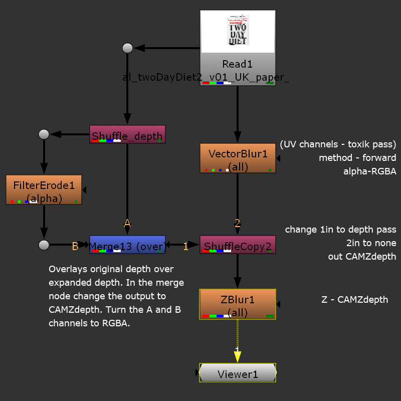
Comping Depth Layer – Zblur

You need shuffle copy the
R value into Nuke “Depth” channel z. This can be piped directly into the Z
attribute (labelled depth.Z) of the Zblur.
ZDefocus – ‘Math’ Attribute
If you’ve
outputted a “camera depth” pass from maya then you’re render will have values
higher than 1. When comping with it in Nuke using the ZDefocus node, set the math
node to “Depth” – this setting will be able to process all those extra high
values above 1, giving a much larger colour range and therefore a more accurate
set depth blur.
If you’ve
rendered out the normalised “camera depth remapped” pass, your values will be
confined to a range of 0 to 1. When comping this pass you’ll want to set your “math”
setting to “far = 0” or “far = 1” depending on what values are on the foreground
and background objects in your render. You can see the values by isolating the
depth pass in the viewer and hovering the mouse over the different parts of the
image – the values will show at the bottom right of the viewer.
ZBlur – focal Plane
You can work out the focal plane based on the depth layer. So, isolate the depth layer and in the viewer hover over the whitest part of the image (the in-focus parts) - at the bottom of the viewer you will get a V value. Enter this value into the focal plane attribute of the ZBlur.
Depth Blurring Motion Vectors
Shuffle out the depth pass and apply an “erode (filter)” node. Change the size value to increase the pixel size. The idea is that the expanded depth pass is big enough to contain the motion blurred beauty pass (controlled by the toxik pass in the vector blur node).
Freishluft – Depth Setup

- move the “focal point” to pick a different value from the depth pass, and pull focus.
- Radius – changes the blur intensity around the focal point.
- Highlight intensity – blows out bright points based on the source RGB images.
- Change the highlight start/end values to enhance the exposure threshold (highlight selection.)
Lens Distortion and Inverse Scale

Undistorting - after running the footage through the Lens Distortion Node you will
need to scale the result with a transform node. Take a note of this scale value
as we’ll need to invert it, when we redistort back after.
Redistort – notice how the nodes are in the opposite order,
this is because we are reversing the process back to what we had previously.
Working out the Inverse
scale on the Transform node
Take the original scale
value and divide 1 by it.
e.g. Inverse scale 1 /
1.152 = 0.868
Alternatively you can
click the ‘invert’ button on the transform node.
Mostly, lenses with a
focal length under 50mm will show any barrel distortion. Anything over 50mm
shouldn’t need undistorting.
Making a Convolved Diffuse HDR
We can break the HDR up into 2 different maps; the original HDR used for reflection information only, and a new “diffuse” HDR which will provide light/brightness information to control the final gather, ambient light only. We can create this new Diffuse HDR using Nukes convolve tool.


Overlay Toggle
Press “O” over the viewer to hide any transform or manipulators, roto shapes.
2D Tracking
1. create tracker node – Transform>tracker.
2. in the tracker node,
turn on “enable use to calculate” to turn on and process a tracker. Once the
tracker is in position either hit #1 to
track forward on the timeline or hit #2 to set
a frame range to track.
3. repeat step 2 to add
more trackers (at least 2 needed for stabilising).
| #1 |
| #2 |
T calculates “translate” information
R calculates “rotation”
S calculates “scale”
4. create another read
node e.g. an image, you want tracked onto the footage. Transform this read node
to the position you want it on frame 1 (or start frame of track).
Stabilise your footage:
In the tracker >
transform tab, change the transform to “stabilise”.
Nuke Directory – shortcut to Roundabout > Jobs
Name: JOBS
Folder: //Roundabout/jobs